


Weight, power, and timing — the three constraints that decide drone integration
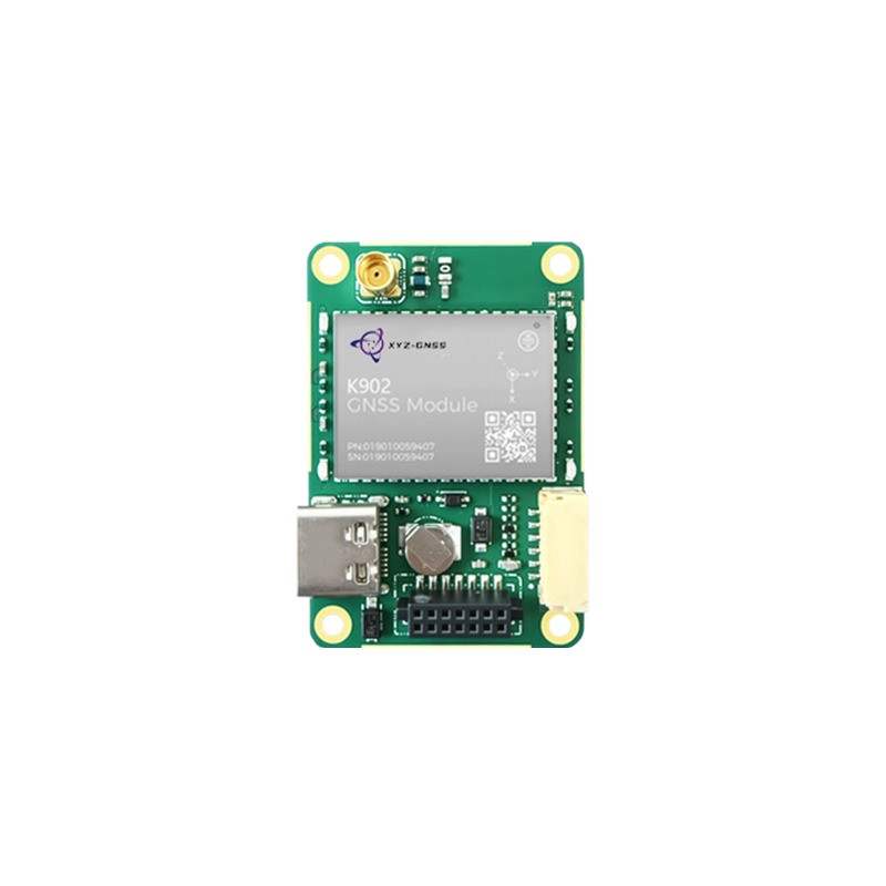
Integrating an rtk gnss module for UAV work is a mass, power, and timing exercise before it is an accuracy exercise. A survey-grade engine that draws more current than the airframe can spare, or that adds two hundred grams behind the centre of gravity, will be rejected regardless of its specification. The engineering task is to find a module whose accuracy, interface, and physical envelope fit an aircraft that was designed before the module was chosen.
This guide covers what a UAV actually imposes on a GNSS module, how accurate the position needs to be for mapping versus for flight control, which interface and timing details matter to the autopilot, and how to plan the correction link so the aircraft is not dependent on a connection that disappears over the survey area.
What a UAV Imposes on a GNSS Module
Four constraints distinguish an airborne installation from a ground one.
- Mass and balance. Every gram behind the centre of gravity has to be compensated. Modules that are a few grams heavier than an alternative change battery placement and flight time.
- Power budget. A high-precision engine can consume an order of magnitude more current than a basic receiver. On a multirotor, that power translates directly into endurance.
- Vibration and thermal environment. Motors and propellers produce high-frequency vibration, and the module may sit in a compartment with poor airflow. Both affect oscillator stability and connector reliability.
- Antenna ground plane. A drone's carbon frame is conductive but not a proper ground plane, and the antenna is usually mounted on a small plate or directly on the shell. This is where airborne installations lose most of their theoretical accuracy.
Absolute Versus Relative Accuracy in Aerial Work
Two different accuracy requirements coexist on the same aircraft, and confusing them leads to overspending on one and underspending on the other.
For mapping and photogrammetry, absolute accuracy determines whether the resulting model sits correctly on the earth's surface relative to existing data. Relative accuracy determines whether features inside the model are correctly proportioned and spaced. Modern processing with ground control points can improve absolute accuracy after the flight, but it cannot fix poor relative geometry caused by unstable positioning during capture.
For flight control, the requirement is different again. The autopilot needs a stable, low-latency position and velocity to hold a hover or fly a waypoint line. Absolute accuracy to the centimetre is less important than consistency, because an offset that is constant simply shifts the mission slightly; an offset that varies causes the aircraft to hunt.
This is why a module for a mapping drone and a module for a delivery drone can be very different parts even though both are described as centimetre-level.
Interfacing With the Flight Controller
| Interface aspect | What the autopilot needs | Why |
|---|---|---|
| Protocol | Native support or a documented parser path | Avoids custom driver work on a safety-critical path |
| Rate | 5 to 20 Hz for navigation, higher for logging | Position hold stability versus bandwidth limits |
| Latency | Consistent and documented | The estimator compensates only if the delay is known |
| Fix status | Distinguish fixed, float, and single | The flight mode may need to change on degradation |
| Timing | Pulse output aligned with capture events | Camera triggering and lidar synchronisation |
The timing output is often the item forgotten until the mapping payload is integrated. If the camera trigger is timestamped by the flight controller rather than by the GNSS, the position assigned to each image carries the jitter of the trigger path, which at survey speed becomes a systematic offset along the flight line.
Heading and Attitude on an Airframe
Most multirotors derive heading from a magnetometer, which is vulnerable to magnetic interference from motors and current-carrying wires. A dual-antenna module provides heading from the GNSS observables and removes that vulnerability, at the cost of a second antenna, a second cable, and a rigid baseline across the airframe.
On a small airframe the achievable baseline may be only 30 to 40 centimetres, which is enough for a coarse but stable heading. For fixed-wing aircraft the baseline can be longer, and the heading is used differently because the aircraft is almost always in motion. In both cases, the structural stiffness between the two antennas determines whether the measurement is usable.
A practical alternative on small drones is to keep a single antenna for position and rely on the inertial system for attitude, accepting a longer initialisation and a periodic yaw re-alignment. The trade is straightforward: one antenna is lighter and simpler, two antennas are more robust in magnetically noisy environments.
Planning the Correction Link
RTK on an aircraft depends on corrections arriving continuously. There are two common arrangements, and each has a failure mode worth designing for.
A local base station on the ground gives full control and does not depend on mobile coverage, but the radio link must cover the entire survey area. When the aircraft flies beyond radio range, corrections stop and the solution degrades. The mission plan should therefore keep the flight inside the link footprint, or use a base with a higher-gain antenna.
A network RTK service removes the base station but depends on cellular coverage and on the aircraft carrying a modem. Over remote terrain that coverage may be absent exactly where the survey is most needed. Many operators now plan for both: network as the default, a local base as the fallback for remote sites.
In either case, the module should report the correction age and the solution type so the ground station can see when the aircraft is no longer fixed. A flight that continues to log positions without that information produces a dataset that has to be reprocessed later.
The base station itself is part of the aircraft's accuracy budget. Placing it on a tripod in the middle of the survey area rather than beside the vehicle improves the baseline geometry for every pass, and recording a short static session at the base gives the processing step a known reference if the coordinates later need to be recomputed. On multi-flight campaigns, keeping the same base position across days removes a variable that otherwise complicates comparing one flight with another.
Yonghao Innovation Modules and Antennas for UAV
Yonghao Innovation Tech is a national high-tech enterprise established in 2014, based in Shenzhen, Guangdong, China. We integrate research, manufacturing, and sales, and we supply GNSS satellite antennas, positioning terminals, data communication products, and customized high-precision BeiDou solutions for surveying and monitoring, aerospace, communication time service, autonomous driving, machine control, and intelligent transportation.
Our RTK GNSS module range includes compact engines intended for airframes. The Mini-Mosaic-G5 provides centimetre-level positioning in a small form factor for drones, robots, and autonomous systems. The ZED-F9P is a widely adopted multi-band module that concurrently uses GPS, GLONASS, Galileo, BeiDou, and NavIC signals, which suits teams that already have supporting tooling and firmware.
Antennas for airborne use are drawn from our UAV product line, and typical airframe configurations are described under UAV projects. Where the airframe requires a specific connector, a shortened cable, or a reduced antenna height, our technical support team reviews the constraint against the existing mechanical platform.
Conclusion
Selecting an rtk gnss module for UAV integration is a balance of mass, power, timing, and interface compatibility, with accuracy as the constraint rather than the objective. Decide first whether the mission needs absolute or relative accuracy, confirm the autopilot's protocol and timing expectations, and plan the correction link for the places the aircraft will actually fly. Addressing those four items before the airframe is finalised avoids the most common outcome in this category: a capable module that the aircraft cannot quite support.
Tell us the airframe class, mission profile, and correction source, and we will suggest a module and antenna pairing that fits the weight budget.
Plan my UAV integration See UAV configurationsFrequently Asked Questions
Q1: How much does an rtk gnss module for UAV add to flight time?
It reduces flight time through mass and power draw rather than through any single figure. High-precision engines consume more current than basic receivers, and the antenna plus cable adds weight. Estimate both against your endurance margin before selecting a module.
Q2: Does an rtk gnss module for UAV improve mapping accuracy automatically?
Only if the camera trigger is synchronised with the GNSS time and the corrections remain valid throughout the flight. Without accurate timestamps, the module's precision does not translate into image georeferencing accuracy.
Q3: Can an rtk gnss module for UAV use a network correction service?
Yes, provided the aircraft carries a modem and the survey area has coverage. For remote sites, a local base station with a radio link is usually more reliable, and many operators plan both options for different mission types.
Q4: Where should an rtk gnss module for UAV be mounted?
As far from the motors and power wiring as practical, with the antenna above the airframe and a metal plane beneath it. The module itself can sit inside the fuselage if the antenna is external and the cable loss is accounted for.
Q5: What happens to an rtk gnss module for UAV when corrections are lost in flight?
The solution degrades to float or single point, and the autopilot should be configured to react — typically by continuing the mission with reduced precision or by returning. The module needs to report the change immediately so the flight controller can decide.